Thursday

H.323 Architecture Protocols and Procedures

H.323 is an umbrella recommendation that depends on several other standards and recommendations to enable real-time multimedia communications. The following are the key H.323 reference recommendations.

Call Signaling and Control

  • H.323: Packet-based multimedia communications systems

  • H.225: Call control protocol

  • H.235: Security

  • H.245: Media control protocol

  • Q.931: Digital subscriber signaling

  • H.450.1: Generic functional protocol for the support of supplementary services in H.323

  • H.450.2-11: Supplemental features: blind call transfer and call diversion, consulting (450.2); call forward, activation/deactivation, interrogation (450.3); call hold (450.4); call park, call pickup (450.5); call waiting (450.6); message waiting (450.7); name interrogation (450.3), call hold (450.4); call park/call pickup (450.5); call waiting (450.6); message waiting (450.7); name identification service (450.8); call completion (450.9); call offer (450.10); call intrusion (450.11)

H323 Annexes

  • Annex D: Real time fax over H.323

  • Annex E: Multiplexed call signaling

  • Annex F: Simple Endpoint Terminal (SET)

  • Annex G: Text SET

  • Annex H: Mobility

  • Annex I: Operation over low QoS networks

  • Annex J: Secure SET

  • Annex K: HTTP service control transport

  • Annex L: Stimulus signaling

  • Annex M: Qsig tunneling

  • Annex N: QoS

Audio Codecs

  • G.711: PCM audio codec 56/64 kbps

  • G.722: Audio codec for 7 Khz at 48/56/64 kbps

  • G.723: Speech codec for 5.3 and 6.4 kbps

  • G.728: Speech codec for 16 kbps

  • G.729: Speech codec for 8/13 kbps

Video Codecs

  • H.261: Video codec for 64 kbps

  • H.263: Video codec for 64 kbps

H.323 Version 1 was approved in 1996. Version 1 centered on multimedia communications, such as voice and video over IP data networks. Version 2 was approved in January 1998, and addressed deficiencies in Version 1 and introduced new functionality within existing protocols, such as Q.931, H.245, and H.225, and entirely new protocols. The most significant advances were in security, fast call set-up, supplementary services, and T.120/H.323 integration. There was more efficiency about getting media streams to transfer at a faster rate. The major functions introduced were Fast Connect (also known as Fast Start) and H.245 tunneling (transferring minimal call signals to more quickly establish connection). Version 3, approved in May 1999, had several new annexes or sections focused on H.323-compliant devices for large-scale production networks. It covered bandwidth management and QoS issues and focused on “smart” networks and “dumb” endpoints (master/slave relationship). Some specific areas addressed were:

  • Connection over UDP

  • Simple endpoint type

  • Interdomain communications

  • H.263 and packetization

  • H.GCP decomposition architecture

H.323 Version 4 was approved in November 2000 and contained many enhancements in a number of important areas, including reliability, scalability, and flexibility. Many of the new features facilitate more scalable gateway and MCU solutions to meet the market requirements for IP telephony. Version 4 addressed the following issues:

  • Gateway decomposition

  • Multiplexed stream transmission

  • Supplementary services

  • Additive registrations

  • Alternate gatekeepers

  • Usage information reporting

  • Endpoint capacity

  • Tones and announcements

  • Mapping aliases

  • Indicating desired protocols

  • Bandwidth management

  • Reporting call status

  • Real-time fax

  • Call linkage

  • Tunneling

  • QoS

  • H.245 in parallel with Fast Connect

  • Generic extensibility framework

  • H.323 URL

  • Call credit-related capabilities

  • DTMF relay via RTP

Tuesday

H.323 Architecture Components

H.323 specifies components, protocols, and procedures for real-time point-to-point and multipoint multimedia communications over packet-based networks. It also sets interoperability guidelines for communication between H.323-enabled networks and the H.32X-based family of conferencing standards.

An H.323 implementation requires four logical entities or components. These are terminals, gateways, gatekeepers, and MCUs. A fifth component element, known as border elements, is optional. Terminals, gateways, and MCUs are collectively known as endpoints. Although an H.323 network can be configured with only terminals, the other components are essential to provide greater practical usefulness of the services.

Terminal

A terminal, or a client, is an endpoint where H.323 data streams and signaling originate and terminate. In an IP-PBX system, it may be an IP telephone; a non-IP communications device, such as an analog telephone with an IP adapter module; or a PC client softphone with an H.323 compliant stack. A terminal must support audio communication; video and data communication supports are optional.

Gateway

A gateway is an optional component in an H.323-enabled network. A gateway will be required if at least one of the terminals does not conform to H.323 standards but is designed for a different type of network. The gateway is usually located at the interface between the two networks. Through the provision of gateways in H.323, it is possible for H.323 terminals to interoperate with other H.32X-compliant conferencing terminals. For example, a PC client softphone station user can talk to a station user on an analog telephone. A gateway provides data format translation, control signaling translation, audio and video codec translations, and call setup and termination functionality on both sides of the network. Gateway equipment is composed of a Media Gateway Controller (MGC) and a Media Gateway (MG), which may co-exist or exist separately. The MGC handles call signaling and other nonmedia-related functions, and the MG handles the media. There are different types of gateways required to support H.310, H.320, H.321, H.322, or H.324 endpoints.

Gatekeeper

A gatekeeper is an optional component of an H.323-enabled network. Gatekeepers ensure reliable, commercially feasible communications and are used for admission control and address resolution. The gatekeeper may allow calls to be placed directly between endpoints or it may route the call signaling through itself to perform functions, such as followme/find-me, forward on busy, etc. A gatekeeper is often referred to as the controller of the H.323 enabled network, because it provides central management and control services. When a gatekeeper exists, all end- points (terminals, gateways, and MCUs) must be registered with it. Registered endpoints’ control messages are routed through the gatekeeper.

The gatekeeper and the endpoints it administers form a management zone. A gatekeeper provides several services to all endpoints in its zone.

Address translation. A gatekeeper maintains a database for translation between aliases, such as international phone numbers, and network addresses.

Admission and access control of endpoints. This control can be based on bandwidth availability, limitations on the number of simultaneous H.323 calls, or the registration privileges of endpoints.

Bandwidth management. Network administrators can manage bandwidth by specifying limitations on the number of simultaneous calls and by limiting authorization of specific terminals to place calls at specified times.

Routing capability. A gatekeeper can route all calls originating or terminating in its zone. This capability provides numerous advantages: accounting information of calls can be maintained for billing and security purposes; a gatekeeper can reroute a call to an appropriate gateway based on bandwidth availability; and rerouting can be used to develop advanced services such as mobile addressing, call forwarding, and voice mail diversion.

Multipoint Control Unit

The MCU is an optional component of an H.323-enabled network. It is responsible for managing multipoint conferences (two or more endpoints engaged in a conference). It consists of a mandatory Multipoint Controller (MC) that manages the call signaling and optional Multipoint Processors (MPs) to handle media mixing, switching, or other media processing. Although the MCU is a separate logical unit, it may be combined into a terminal, gateway, or gatekeeper.

The MC provides a centralized location for multipoint call set-up. Call and control signaling are routed through the MC so that endpoint capabilities can be determined and communication parameters negotiated. An MC may also be used in a point-to-point call, which can later be extended into a multipoint conference. The MC may also determine whether to unicast or multicast the audio and video streams depending on the capability of the underlying network and the topology of the multipoint conference.

The MCU is required in a centralized multipoint conference, where each terminal establishes a point-to-point connection with the MCU. The MCU determines the capabilities of each terminal and sends each a mixed media stream. In the decentralized model of multipoint conferencing, an MC ensures communication compatibility, but the media streams are multicast and the mixing is performed at each terminal.

Border Elements

Border elements are often colocated with a gatekeeper. They exchange addressing information and participate in call authorization between administrative domains. Border elements may aggregate address information to reduce the volume of routing information passed through the network and assist directly in call authorization/authentication between two administrative domains or via a clearinghouse.

Sunday

H.323 Benefits

IP-PBX system designers gain several important benefits by using the H.323 recommendations for support of IP telephony. One of the most important is an open system design because H.323 is not proprietary to any hardware equipment or operating system. There is a multitude of products that support H.323 standards and provide IP-PBX system designers with a flexible choice of system components and solutions. Major system hardware elements, such as servers and clients (telephones, PCs), are available from dozens of sources. Proprietary hardware is associated with circuit switched PBXs and is something IP-PBX system designers hope to avoid. Standards for voice and video codecs and for the compression and decompression of digital bit streams are also established under H.323, ensuring communications and networking between systems from different manufacturers. H.323 also establishes methods for receiving clients to communicate their capabilities to sending clients to establish common call set-up and control protocols, because it is important for clients in different corporate networks to communicate with each other.

The fact that H.323 is designed to operate on top of common network architectures is another important factor in the IP-PBX system open design concept. Network technology is constantly evolving, as are bandwidth management and applications services over the network. Systems based on H.323 standards can evolve as networks evolve. Dependency on one type of network or the currently installed network would limit the functional growth of an IP-PBX system. Many users may want to conference LAN clients to a station user at a remote site. H.323 establishes a means of linking LAN-based desktop systems with ISDN-based group systems. H.323 uses common codec technology from different audio- and videoconferencing standards to minimize transcoding delays and provide optimum performance.

An important PBX feature is multiparty conferencing. H.323 supports conferences of three or more endpoints without requiring a specialized MCU, but the H.323 MCU element can support a more powerful and flexible architecture for hosting multipoint conferences. The MCU element can be embedded in a variety of H.323 system components. H.323 also can support multicast transport in multipoint conferences. Multicast sends a single packet to a subset of destinations on the network without replication. Multicast transmission uses bandwidth more efficiently than unicast or broadcast methods of transmission because all stations in the multicast group read a single data stream. An H.323 conference also can include endpoints with different communication media capabilities. For example, a telephone with audio-only capabilities can participate in a conference with workstations that have audio, video, and data capabilities. Further, an H.323 multimedia terminal can share the data portion of a video conference with a T.120 data-only terminal while sharing voice, video, and data with other H.323 terminals

H.323 also addresses bandwidth management in support of bandwidth-intensive audio and video traffic. The network manager can control the number of simultaneous H.323 connections within a network or the amount of bandwidth available to H.323 applications. Limiting connections (conversations) across the network ensures that critical traffic will not be degraded. The QoS issue is one of the most important facing IP-PBX growth because many customers have problems addressing increased traffic load on their networks. Voice communications is very sensitive to delays, packet loss, and other network problems that do not affect data traffic to the same degree. Assuming that a significant amount of voice traffic will be transmitted on LAN networks based on a mix of old and new equipment originally configured for non–real-time communications, achieving acceptable QoS levels is one of the greatest barriers facing IP-PBX market penetration. Security of voice communications over LANs and WANs is another customer concern addressed by H.323. The H.323 recommendation provides authentication, integrity, privacy, and nonrepudiation support.

Friday

VoIP Standards and Specifications

Internet telephony is the transport of telephone calls over the Internet. The process of supporting voice calls over the Internet using the Internet communications protocol IP, is known as Voice over IP (VoIP). The first business customer implementations of VoIP were long distance calls over an IP WAN as an alternative to traditional PSTN trunk facilities. Network gateway servers had converted PBX TDM/PCM signals into IP format for transport through a router network. VoIP offered no new features or functions, merely an alternative means of transport. VoIP was not used for station-to-station on-premises calls, and IP control signaling was not used for call set-up or feature activation. As the new technology evolved to include PBX system desktop call control signaling and communications over an IP network infrastructure, ToIP gradually started to replace VoIP. VoIP is still the most commonly used term, although ToIP is being used more to describe the workings of an IP-PBX system.

There are several sets of VoIP communications protocols that can be used by an IP-PBX system for call control signaling and communications transmission. Circuit switched PBXs were based on proprietary call control signaling to the digital desktops and used TDM/PCM standards for transmission across internal switching networks and to network with other communications systems over PSTN trunk carrier facilities. It was the intention of the early IP-PBX system developers to use open standard communications protocols over packet switched networks as a counter to the closed, proprietary nature of circuit switched PBXs. The communications protocol of choice used by most first-generation IP-PBX system designers was the ITU-T H.323 series of protocols. A competing standards body, the IEFT, developed Session Initiation Protocol (SIP). Many IP-PBX manufacturers are planning to offer SIP versions of their current systems based on H.323, but the first product offerings will not be commercially available until later this year. SIP may offer several advantages over the ITU-T’s recommendation, but the momentum of H.323 will delay saturation of the IEFT’s solution to VoIP communications systems for several years according to the major IP-PBX manufacturers.

ITU-T H.323

ITU-T H.323 is a set of protocols for voice, video, and data conferencing over packet switched networks such as Ethernet LANs and the Internet that do not provide a guaranteed QoS. The H.323 protocol stack is designed to operate above the transport layer of the underlying network. H.323 uses the IP for internetwork conferencing.

H.323 was originally developed as one of several videoconferencing recommendations issued by the ITU-T. The H.323 standard is designed to allow clients on H.323 networks to communicate with clients on other videoconferencing networks. The first version of H.323 was issued in 1996 and designed for use with Ethernet LANs. H.323 Version 1 borrowed much of its multimedia conferencing aspects from other H.32x series recommendations. H.323 is part of a larger series of communications standards that enable videoconferencing across a range of networks. This series also includes H.320 and H.324, which address ISDN and PSTN communications, respectively.

H.323 is known as a broad and flexible recommendation. Although H.323 specifies protocols for real-time point-to-point voice communication between two terminals on a packet switched network, it also includes support of internetwork multipoint conferencing among terminals that support not only audio (voice) but also video and data communications.

H.323 recommendations can be summarized as followed.

Point-to-Point and Multipoint Conferencing Support

H.323 conferences may be set up between two or more clients without any specialized multipoint control software or hardware. If an MCU is used, H.323 supports a flexible topology for multipoint conferences. A multipoint conference can be centralized so that new participants can join all the others in the conference. A multipoint conference may also be decentralized so that new participants can elect to join one or more participants, but not all participants, in the conference. The centralized approach is a star topology; the decentralized one is a mesh topology.

Internetwork Interoperability

H.323 clients are interoperable with clients on circuit switched networks such as those based on recommendations H.320 (ISDN), H.321 (ATM), and H.324 (PSTN/Wireless). For example, it is possible to call from an H.323 client to a regular telephone on a PSTN. At the corporate level, this internetworking capability allows enterprises to migrate voice and video from existing networks to their own data networks.

Heterogeneous Client Capabilities

An H.323 client must support audio communication. Support of video and data communications is optional. During call set-up, capabilities are exchanged and communication established based on the lowest common denominator.

Audio and Video Codecs

H.323 specifies a required audio and video codec, but there is no restriction on the use of other codecs. Clients are allowed to decide which codec to use.

Management and Accounting Support

H.323 calls can be restricted on a network based on the number of calls already in progress, bandwidth limitations, or time restrictions. Policy management guidelines are used for H.323 traffic control. H.323 also provides accounting facilities that can be used for billing purposes.

Security

H.323 provides authentication, integrity, privacy, and nonrepudiation support.

Supplementary Services

Recommendation H.323 provides a basic framework for the development of application services, similar to the call processing features typically supported by a PBX system. This effort began with H.323 Version 2, which standardized a few services with recommendation H.450, including call transfer and call forwarding.

Wednesday

The Case for the Client/Server IP-PBX

A client/server IP-PBX is likely to be the standard design platform of the future for enterprise communications systems. Although there are several drawbacks to current client/server IP-PBXs, there may be several benefits to customers who select it as their enterprise communications solution. Recalling the pricing discussion in the preceding paragraphs, the upfront capital investment for a client/server design is favorable for customer solutions with the following characteristics:

  • Green field location

  • Large percentage of IP peripherals, such as telephone instruments

  • Remote location requirements with small port capacities

  • Small port capacity requirements with PBX performance requirements

Green field locations without existing PBX equipment and with the newest generation of LAN switches and IP routers that can be programmed to support voice-grade QoS levels are best suited to cost effectively support a client/server design. A client/server design that supports a significant number of IP stations and minimal analog communications equipment will be more optimally priced, and support of remote IP stations likely will be less expensive than circuit switched alternatives. Customers with KTS/Hybrid port capacity requirements, but who require the performance capabilities of a larger, more complex PBX system, are likely to discover that the price of a client/server design is a more attractive alternative to a full-featured circuit switched or converged system solution.

The most common reasons given by system suppliers to promote the performance value of a client/server IP-PBX are:

  1. Using a converged network for a variety of communications media: voice, data, video, text, graphics

  2. Universality of IP transport

Figure 1: Basic client/server IP/PBX design.
  1. Lowered communications bandwidth requirements and more efficient use of existing bandwidth

  2. Simplified centralized management and administration

  3. Rapid deployment of new technology and applications

  4. Fully distributed network design

  5. Scalability

Converged Network

The concept of the integrated voice/data PBX system in the early 1980s was driven by the increasing amount of data traffic generated by geographically dispersed desktop CRT terminals linked to a centralized host processing system. It was thought that the circuit switched telephony network could be used to carry voice and data enterprise communications traffic. The advent of Ethernet LAN hubs and switches in the mid-1980s effectively ended the dream of the PBX system as an all-media office systems controller. Today the pendulum has swung the other way; packet switched LANs carry telephone-generated voice communications in addition to PC client data traffic. To data communications network designers and managers, the telephone is viewed as just another client, and voice features and functions are just other applications supported by a LAN-based server. If a customer is seriously thinking about migrating to an IP-PBX system, then a client/server design using the existing LAN/WAN infrastructure is the optimal solution. As LAN bandwidth capacity continues to increase, more video communications traffic will be carried between desktops with decreasing dependence on larger, more expensive, room-based videoconferencing systems.


Figure 2: IP-PBX pricing: converged versus client/server.

Universality of IP Transport

Ten years ago the Internet was used almost exclusively by government and higher education institutions. Today the Internet is everywhere, and IP control and transmission signaling have become the standard for data communications networks. There is universal access to LANs and WANS in all medium and large enterprises across all industry sectors. The client/server enterprise data communications network design has replaced the host mainframe design that was dominant in the 1970s and most of the 1980s, and IP networking has replaced IBM’s Systems Network Architecture (SNA) as the standard. If a customer is looking at an IP-PBX system solution, the current data networking infrastructure is favorable to a client/server design.

Network Bandwidth

Using the same communications network for voice and data traffic reduces overall bandwidth requirements because the two traffic streams can be interleaved and QoS levels can be engineered and programmed to satisfy real-time voice communications requirements. There will be cost savings and increased network efficiency due to economies of scale as a customer migrates an increasing percentage of traditional circuit switched PBX traffic to the packet switched LAN/WAN. The major bandwidth cost savings and optimization will be attributed to off-prem- ises communications because circuit switched PSTN trunk carrier facility requirements can be reduced.

Simplified Centralized Management and Administration

A single communications management system is less costly to operate and more easily administered than separate systems for voice and data communications. The primary elements of an IP-PBX client/server design—desktop IP telephones and telephony call server(s)—are indistinguishable to a data network management system when compared to with PC clients and a data processing server or database manager. All voice system moves, adds, and changes are performed from the data network management workstation, as are maintenance and service operations.

Rapid Deployment of New Technology and Applications

A client/server design lends itself more to rapid deployment of new technology and applications because there are fewer hardware elements in the system architecture than in a converged IP-PBX that retains the traditional proprietary common equipment components of a circuit switched PBX. It is far easier to implement a technology upgrade for a client/server IP-PBX because there are fewer if any, proprietary switching network elements, and new advanced applications can be implemented through a software upgrade or an optional applications server. Client/server designs based on third-party servers are easily upgraded and enhanced by replacing the existing server with a newer, more powerful server. Migration between client/server IP-PBX generations will be smoother and less disruptive than between converged system generations that are based on more proprietary and costly common equipment hardware.

Fully Distributed Network Design

A client/server IP-PBX is by definition a distributed network design. A single telephony call server can support premises and off-premises IP stations. Premises stations can be distributed in a single building or across a campus. Multiple server designs can be programmed to support redundant emergency call processing in case of individual server failure. The servers can be colocated or distributed for disaster recovery situations. Customers have multiple layers of LAN/WAN switching and routing that preclude single points of failure.

Scalability

A client/server design has the potential to be highly scalable because IP telephones are easily added to the system without the need for specialized port interface circuit cards, and port capacity can be expanded through the addition of another server. Converged IP-PBXs require port interface cards, if only for control signaling, and, except for the rare system model based on a distributed processing design, there are call processing and port capacity limitations when using a single common control complex. The switching and transport limits of a client/server design are virtually boundless because a customer can continually install switches and routers to the LAN/WAN infrastructure to support increased traffic or more stringent QoS levels.

There are many customers for whom a converged or client/server IP-PBX system design will satisfy financial, feature performance, and applications requirements. Many enterprise communications system customers may also decide that their circuit switched PBX system will continue to be a satisfactory solution for current and near-term needs. A customer may not be ready to immediately replace his legacy PBX system with an IP-PBX system, but should seriously consider testing ToIP technology very soon.

Monday

The Case for Converged IP-PBX Systems

There are several advantages for implementing a converged IP-PBX system or a client/server IP-PBX. First let’s review the case for the converged IP-PBX system.

A converged IP-PBX system occupies the gray zone between the traditional PBX system and the evolving client/server design because it can offer customers the best of both worlds: the reliability, redundancy, and feature/function performance benefits of legacy circuit switched PBXs and the unique capabilities of ToIP technology to leverage LAN/WAN infrastructure in support of dispersed common carrier equipment and desktop terminals. A converged PBX system is best viewed as a bridge between the existing circuit switched world of voice communications and the emerging packet switched world. Instead of attempting to leap from the old world to the new world in one jump, it makes more sense to travel a longer, but less risky, road.

A converged IP-PBX system and an IP packet switched client/server platform can provide each of these customer benefits. The latter solution is usually optimized in a green field situation—a new customer location without a previously installed system, although a customer may still elect to install a converged system for incremental migration from a circuit to a packet switched solution. Many customers with an existing circuit switched system installation are likely to upgrade to a converged system with a minimal investment in new hardware and/or software. In contrast, a client/server design represents a major design break from previously installed circuit switched PBX systems and entails replacement of most existing common equipment and desktop terminal instruments.

The following are probable reasons a customer requiring ToIP capabilities might choose a converged IP-PBX system solution instead of an IP packet switched client/server design:

  1. ToIP requirements

  2. Investment protection

  3. Critical reliability

  4. Private network compatibility

  5. Feature requirements

  6. Pricing

ToIP Requirements

A large number of PBX system customers may not currently require ToIP capabilities for their enterprise communications system, although future plans are very likely to require support of ToIP options. A converged IP-PBX system is fully capable of being configured without any IP-based elements at initial installation but can support such a requirement when needed. The group of customers who are risk-averse may also choose to delay installation of ToIP options at the present time because they are taking a wait-and-see attitude toward the emerging technology. Early versions of products incorporating new technology may not satisfy accepted benchmark reliability standards for telephony applications. In addition, ToIP standards are still in a state of flux, and customers may wish to wait until control signaling protocol and voice codec standards have stabilized. Some first-wave customers who installed IP-PBX systems shortly after product introduction have watched as evolving standards and system upgrades obsoleted their installed terminal equipment, voice codecs, and/or telephony servers. A converged IP-PBX reduces this risk by allowing customers to upgrade and enhance their system for active ToIP capabilities when the time is acceptable.

A converged IP-PBX system is also ideal for customers who wish only to test ToIP technology without installing a 100 percent IP peripheral solution. For trial purposes it is less costly to use a converged IP-PBX system that is also functioning as the full-time circuit switched communications system than to purchase and install a dedicated IP packet switched client/server design. For trial purposes, a select number of IP peripherals can be installed on a converged IP-PBX system. If the trial is successful, additional IP ports can be equipped and activated when needed. A very important factor in the successful implementation of an IP-PBX system is the LAN/WAN infrastructure, because the network must be properly designed and programmed to provide an acceptable Quality of Service (QoS) level for real-time voice communications applications. A small-scale IP-PBX trial is usually necessary to discover in advance whether or not a major LAN/WAN overhaul is needed. What works on paper does not always work in real life. Using a converged IP-PBX system is the most efficient solution for trial testing ToIP QoS levels for station and/or trunk traffic communications.

Investment Protection

All customers make substantial financial and organizational investments in their installed premises communications system and usually seek to maximize their return on investment (ROI). Replacing an installed circuit switched PBX system with a new IP packet switched client/server design solution at the present time may be counter to this customer objective. For example, a customer may not have fully depreciated the installed system’s common equipment and desktop terminals. Replacing cabinet and port interface hardware with a telephony call server and gateways and digital telephones with new IP telephones is an expensive proposition, as are major upgrades to the LAN/WAN infrastructure to support real-time voice-grade QoS levels. Training expenses for station users, system managers, and maintenance personnel also add to upfront cost outlays. Additional costs are associated with a disruption of communications operations and procedures when migrating from an installed system to an entirely new platform. Although the data communications world has grown accustomed to constant change, one of the most fundamental characterizations of the voice communications world is reluctance to change.

Upgrading an installed circuit switched PBX system to a converged IP-PBX system is less costly than overhauling the entire communications system and network and is typically a far less disruptive experience because most station users are likely to retain their legacy desktop terminal equipment over the short term. The few station users who migrate to a ToIP desktop are more easily trained and supported in this environment. All of the features and functions available to station users before the system upgrade will remain available afterward, which is not usually the case if the legacy common control design is replaced with a new telephony call server loaded with a different software package.

PBX life cycles have fluctuated during the past several decades. Before the introduction of the computer-controlled digital PBX in the 1970s, the typical installed life of a PBX system was greater than 10 years. PBX systems did not change significantly over short periods. During the 1980s, the typical PBX life expectancy shrunk to between 6 and 8 years because of continual major design changes and dramatic software program upgrades. Since the early 1990s, the life cycle of an installed PBX system has slowly been increasing because system designers have become more cognizant of product migration strategy and its effect on market positioning and sales. Another reason for increased system life is that an increasing number of recent system performance enhancements and upgrades had minimal effect on the core processing and switching system design, because they were focused on peripheral server applications. The concept of upgrading an older PBX system to the current platform instead of the earlier system forklift approach makes possible a cost effective and operationally efficient migration from a circuit switched design platform to a converged circuit/packet switched system.

Upgrading a circuit switched PBX system to a converged IP-PBX system may be as simple as adding a few new port interface cards that provide ToIP gateway and gatekeeper functions for IP peripherals (stations, trunk). A gateway used for ToIP applications is defined as a device that provides a translation, or conversion, between IP and TDM/PCM signaling protocol and communications signals. There must be a physical and logical interface between circuit and packet switched communications networks. A gatekeeper performs or facilitates several basic call control functions within an IP communications network: peripheral equipment registration with the network; address translation of LAN aliases (i.e., telephone directory numbers into IP addresses); and bandwidth management of LAN/WAN network resources. The gatekeeper function in a pure IP communications design is similar to the call control processor in a traditional PBX system. Additional interface cards may be required for support of remote cabinets and port carriers when using the LAN/WAN to transport intercabinet signaling for call control and voice communications traffic. In some cases there may be a requirement for a call processing and/or system memory upgrade. It is most likely that a generic software release upgrade would be required unless a very recent software release is already installed.

A sizable percentage of the current installed base of circuit switched PBX systems can be upgraded to a converged IP-PBX system platform with the hardware/software additions just described. It is estimated that more than 65 percent of the current installed PBX base can be upgraded to a converged IP-PBX system without a major system overhaul. As the oldest installed PBXs are replaced or upgraded, the percentage of upgradeable systems will continue to increase. More than two-thirds of currently installed circuit switched PBXs can be upgraded in place to a converged IP- PBX system platform while protecting up to 90 percent of a customer’s original hardware/software investment. Examples of circuit switched PBXs installed during the past decade that are easily upgraded to a converged system include Avaya Definity ProLogix and ECS models, Nortel Networks Meridian models (Option 11C/51C/61C/81C), Siemens Hicom 300 models, and NEC NEAX 1000/2000/2400 models. These systems alone represent almost two-thirds of the North American installed PBX system base.

Critical Reliability

Traditional circuit switched PBX systems are known for their high reliability standards. The frequently quoted 99.999 percent system reliability benchmark is not a marketing gimmick but the reality. Five “9s” does not apply to every system PBX system component, such as a port circuit card, but to overall system availability. Individual port circuit cards or telephone instruments occasionally may fail, and software glitches may cause a feature failure or call disconnect, but total system failure is a rarity in the world of telephony. The reason for high system reliability, as a result of very low PBX system component failure rates, commonly expressed as Mean Time Between Failures (MTBF) or Mean Time Between Outages (MTBO), is that many system operations are supported by redundant hardware and/or software elements and great care in the electronic design and manufacture of hardware components. During the past decade, most PBX customers have installed and operated their communications systems without ever experiencing a catastrophic failure. Traditional circuit switched PBX technology has reached the bottom plateau of the failure rate curve. In case of failure, redundant system elements, such as main processor boards, system memory storage, switch network and transmission paths, and power supplies, are usually duplicated in a hot standby mode for intermediate and large PBX system models from many, but not all, system suppliers. For example, the Siemens HiPath 4000 and NEC NEAX 2400 IPX systems offer optional duplication of the listed critical system elements.

Although a converged IP-PBX is designed and equipped with several new hardware components and its software generic program includes new features and functions, the system, for the most part, is based on tried and true technology. The most important architecture element of any PBX system design is its common control complex, whether it is based on a proprietary cabinet carrier equipped with several printed circuit board modules or a third-party processing server. All PBX functions begin and end under the control and supervision of the common control complex. Traditional circuit switched PBXs and the upgraded converged IP-PBX version are based on the same common control complex, with perhaps a few modifications, such as an upgraded processor board. The hardware and software components and the core internal diagnostics, maintenance, and management functions remain basically unchanged when the system is upgraded to support ToIP capabilities and applications. The catastrophic failure rate should remain at (or be very close to) the expected 99.999 percent level. Unless an expensive fault tolerant server is used in the client/server IP-PBX system design or a dedicated back-up server is available, the common control reliability level will be less than that offered by a converged IP-PBX system. It should be noted that no client/server IP-PBX system currently uses a fault tolerant server, and very few are currently available with a backup server option.

The reliability of the PBX center stage switch complex is also a very important system factor for minimizing occurrences of catastrophic failure and supporting communications connections. In a converged IP-PBX, the center stage switch function is necessary for all calls among circuit switched peripherals and calls between circuit switched and packet switched peripherals. A client/server IP-PBX design makes use of LAN/WAN switches and routers for all call connections, even calls originating or terminating at non-IP ports. Although some converged IP-PBXs are based on a redundant internal switch network design with numerous duplicated hardware elements, a redundant LAN/WAN design requires multiple switches and routers at the Layer 2 and Layer 3 network levels for redundant connections and transmission paths for calls. More equipment is needed, more communications links must be supported, and more overhead costs are incurred. A configuration with a sizable number of non-IP peripherals in the IP-PBX configuration favors a design with traditional circuit switching capabilities in addition to ToIP capabilities. Except in a few isolated situations, there are very few intermediate/large customer installations that have mandatory requirements for 100 percent IP station users. Until the percentage of IP desktops outnumbers traditional analog and digital desktops, the converged IP-PBX system solution may be the preferable solution for customers with ToIP requirements.

Private Network Compatibility

There has been significant growth in the number of PBX private networks during the past 20 years. Private networks initially were limited to Fortune 500–type customers who had sufficient traffic volume to justify expensive private line facilities. The boom in private networks can be traced to the introduction of virtual private networking (VPN) services in the 1980s, such as the AT&T’s Software-Defined Network (SDN), and the continuing decline in private line lease rates that coincided with the increased availability of wideband and broadband digital carrier facilities. Many present-day private networks are based on a mix of private lines and virtual network facilities and provide a high degree of feature-transparent operation across PBX system locations.

Intelligent feature transparent networking requires a common PBX system platform for optimal transparency of feature/function operation. The evolving Qsig.931 standard for interoperability between dissimilar PBX systems currently provides a limited level of transparency among most of the leading PBX systems. Although a Qsig-based private network implementation may be adequate for some customers, it is not an acceptable solution for most customers. A multisystem network, including PBXs from a variety of suppliers, does not lend itself to a unified systems management solution. The option to centralize network and systems management functions at one location is not currently available in a mixed system platform network. There are other network issues to consider, such as feature/function and desktop terminal uniformity. Unique features on one system cannot be supported transparently across the network to be enjoyed by all stations users. If station user interfaces and telephone instruments are not standardized across the network, training costs increase and station user productivity is affected when an individual moves between network locations.

Taking into account these private networking issues, a customer wishing to migrate from a circuit switched PBX to an IP-PBX is best served by upgrading the installed system to a converged system platform. The upgraded and converged IP-PBX system will retain existing networking capabilities, and station users will have continued access to their accustomed feature sets. A few converged IP-PBX offerings, such as the Siemens HiPath 3000/4000 families and NEC NEAX 1000/2000/2400 families, provide IP station users the option of simply adding an IP adapter to the installed digital telephone or installing a replacement IP telephone with the same look and feel as the older digital telephone model. Replacing a circuit switched PBX system with a client/server IP-PBX system from another supplier will reduce networking performance and force station users to learn how to use a new telephone to access and implement a different feature set.

Feature Requirements

Each customer has unique feature requirements, although there is a common core of features on most everyone’s shopping list that is available with most every PBX system, regardless of switching technology or architecture design. A survey of the leading circuit switched PBX systems indicates that there are at least 500 software features that support a wide range of customer applications, ranging from basic station user desktop features, such as Call Forward, to advanced contact center ACD features, such as ACD agent skill profiling. Most station users, when surveyed, will come up with a list of fewer than a dozen PBX features that they commonly use in their everyday workplace. This does not mean that PBX systems should have a much smaller set of features because the typical station user uses a small percentage of currently available features.

Different station users use different features, and it is likely that in a large system environment a very high percentage of the available PBX features are used by at least one of the system’s station users or administrators. Unique user populations within the PBX system make use of different features groups, such as attendant features, message center features, or ACD features. There are also many PBX features that station users are not aware of that support high-level system operations that are activated concurrently with many station users operations, such as CDR for off-premises calls, or Automatic Route Selection (ARS) when placing long distance calls.

Most of the currently marketed circuit switched PBX systems have software feature packages based on more than 20 years of additions, upgrades, and enhancements. A converged IP-PBX based on its antecedent circuit switched system platform would share the same highly developed and refined feature package, with no sacrifice in performance potential. Very few client/server IP-PBXs are based on previously available circuit switched PBX software feature packages. Most of the first-generation client/server designs are from system suppliers relatively new to the communications system market, with less than 5 years of software feature development. In addition, a few experienced PBX system manufacturers currently offer client/server IP-PBXs with far fewer features and functions than are available with their traditional circuit switched systems.

An analysis of the currently available client/server IP-PBX systems reveals that there are several functional areas where these new system designs are likely to be feature deficient when compared with circuit switched or converged system designs. Feature/function gaps are most common in attendant position, ACD, and private networking. There is also the occasional missing desktop station user feature that has been a longtime standard offering on circuit switched that customers cannot do without.

It has been the standard practice for customers to always ask for more features and functions in their new communications systems in addition to the features they have in their currently installed PBXs. Upgrading to a converged IP-PBX would satisfy this requirement. Replacing a circuit switched PBX system with a client/server IP-PBX that lacks more than a few traditional features and functions should not be acceptable because a smart customer does not trade a few new ToIP features for longtime available features.

Pricing

Price is a concern for all customers across all market segments. Very few customers have unlimited funds for their next communications system purchase. Among all the customer purchase criteria, pricing is the most prevalent. Every PBX system configuration has its own price point, and few customer configurations are identical. One cannot say that a converged IP-PBX is always priced higher or lower than a client/server IP-PBX because it is configuration dependent. Based on current pricing schedules, however, comparisons between the two IP-PBX design types can be made for specific defined configurations, and there are several pricing model assumptions that are usually valid regardless of system model:

  1. An IP telephone is priced higher than a digital telephone with comparable capabilities, such as line appearances, programmable feature buttons, display field, speakerphone option.

  2. Analog station (telephones, fax terminals) and PSTN trunk circuit connections are more expensive with a client/server design because gateways are more expensive than the traditional port circuit cards used in converged IP-PBXs.

  3. Emergency power costs are greater for a client/server design because there is more distributed hardware equipment, such as telephony call servers, database servers, Ethernet switches, routers, and desktop terminals.

  4. The cost to add an incremental IP port to a converged IP-PBX is greater than a client/server design because the converged system requires a port circuit card housed in a port carrier to support the added port.

  5. Cabling costs for a green field installation are less for a client/server design than for a converged design.

Adding a few IP ports to a circuit switched PBX upgraded to a converged system will naturally be far more cost effective than replacing the entire system with a client/server design. If a significant number of IP ports are required, however, the cost of a client/server design is likely to be less expensive because the only significant variable cost is the price of a telephone. Converged systems require gateway/gatekeeper function port circuit cards to support IP telephones and/or IP trunk circuit connections for non-IP stations.

Figure 1 and 2 shows the two types of IP-PBX designs at a fixed port capacity. The customer configuration assumes a mix of single-line analog telephones, multiple-line telephones (digital or IP), PSTN local trunk circuits, and private network trunk circuits (PSTN or IP WAN). Design requirements such as redundancy (call processing, memory storage, power, switching) can significantly influence the shape of the two curves, as can advanced application requirements, such as contact centers, but the general trend lines would remain the same.

Figure 1: IP-enabled circuit switched PBX.

Figure 2: TDM/LAN IP-PBX.

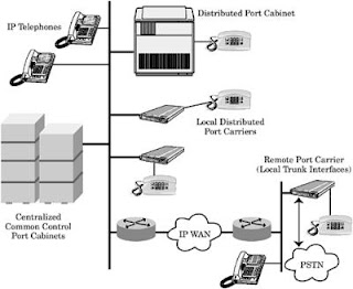
Major differences in the design types are best exemplified at the two extremes of the price plots, 0 percent and 100 percent IP ports. At minimal mandatory IP port requirements, a converged system is priced significantly less than a client/server design that is ill-suited to support non-IP ports, despite a lower cost for common control and reuse of LAN switches and IP routers, because IP telephones are more expensive and support of analog devices is very expensive. At maximum IP port requirements, a converged system is priced significantly more than a client/server design because of the requirement for gateway/gatekeeper port circuit cards. As mandatory IP port requirements increase, a client/server design is the favored solution because higher priced IP telephones are offset by reduced common equipment and wiring costs as compared with a converged solution.

A few closing comments regarding IP-PBX system pricing:

  1. Client/server designs are priced lower than converged solutions as mandatory IP port requirements increase and/or traditional circuit switched port requirements decrease.

  2. Green field environments are optimal for client/server designs because the newly installed LAN/WAN infrastructure can be initially designed and voice-grade QoS, and a single cabling system can be installed for all media communications needs.

  3. Upgrading a circuit switched PBX to a converged IP-PBX system is more cost effective than replacement with a client/server system, regardless of IP port requirements, because the common control complex and cabinet equipment is already in place and paid for.

Saturday

IP-PBX SYSTEM: Benefits and Advantages

There are several important reasons why customers may decide to implement an IP-PBX system for enterprise communications.

Leverage Existing Investment in LAN/WAN Infrastructure

During the past decade customer investment in LAN/WAN infrastructure has greatly exceeded investment in traditional circuit switched voice communications systems. The current installation life of a typical customer’s LAN/WAN equipment is much shorter than their PBX system. Financially, it makes sense to leverage the more up to date LAN/WAN equipment, rather than the older PBX system, to satisfy current and future growth and application requirements. The residual value of circuit switched PBX system components is rapidly declining because the future of voice communications increasingly will depend on packet switched LAN/WAN infrastructures.

Using a single cabling and network infrastructure for voice and data communications applications instead of the traditional two network approach offers customers several advantages: reduced upfront capital expenditures and ongoing maintenance and service expenses, simplified installation and management/maintenance operations, and use of LAN/WAN by an increased number of station users.

Reduce Capital, Network, and Operating Expenses

Using a single network infrastructure for all communications media requirement reduces upfront capital expenditures, monthly network service costs, and operating expenses. Although the current price for an IP-PBX system may not always be less than that of a circuit switched PBX system, the projected cost curve favors the former solution in the future. IP telephone instrument prices will continue to decline as product levels increase. Eventually, many of the equipment cost components of a circuit switched PBX system will be eliminated in a ToIP environment, including port carriers and printed circuit boards, in support of desktop peripherals and trunk circuit interfaces. The cost of a telephony server will be less than that of existing common control complexes.

Using the existing data communications network to support voice networking requirements across multiple customer locations may significantly reduce telecommunications service expenses. WAN-based trunk connections require less bandwidth because of voice compression techniques and packet routing network configurations. Fewer trunk circuits translate to reduced expenses. The growth of broadband optical fiber networks will make bandwidth a non-issue for voice communications. Voice over IP (VoIP) trunking on IP-PBXs is currently limited to private network applications, but eventually will expand across different customer enterprise networks.

Operations, administration, and maintenance (OA&M) expenses are always greater than equipment and telecommunications service costs because of personnel expenses and outlays (salary, benefits, training, and tools). Price curves for equipment and telecommunications services typically decline, but personnel costs always rise. Reducing OA&M expenses is possible only by reducing personnel requirements. One communications network will save on maintenance personnel costs, and the greater centralization of management administration staff will further reduce costs. The days of separate voice and data communications management staffs are slowly coming to an end.

Simplify System and Network Configuration Upgrades and Expansion

The most beneficial ToIP technical advantage is the ease of adding station users and supporting dispersed geographic locations to an existing system configuration. Using the ubiquitous LAN/WAN infrastructure to interface individual station users or groups of station users simplifies network configuration upgrades and expansion. Remote individual IP station users do not require local PBX common equipment (carriers, port circuit cards) to interface to the voice communications system. Using the LAN/WAN to support remote carrier cabinet requirements for station users within a campus setting or across multiple premises eliminates the need for dedicated circuit switched trunk links for signaling and communications. The distributed capabilities of an IP-PBX can also reduce the need for multiple systems in a network configuration. A single system configuration offers several significant benefits over a multisystem network solution, including full feature/function transparency across locations, simplified systems management and administration, and reduced system upgrade costs over the life of the system—one system upgrade, when needed, instead of system by system upgrades.

The underlying technology of an IP-PBX system offers greater configuration scalability than traditional circuit switched systems because it may be simpler and more cost effective to add stations and/or port carriers using the LAN/WAN infrastructure as the cabling and transmission system. For example, IP telephones can use existing Ethernet data ports to connect into the voice communications network, or remote station users using a PC softphone can dial into the LAN/WAN for system access and connectivity. An IP-PBX system reduces the need for interface outlets and wiring dedicated to voice-only communications.

Conforms to Standards

Circuit switched PBXs were traditionally designed to use proprietary signaling protocols in support of call processing and switching functions. Except for ISDN BRI telephones, all digital PCM-based telephones are proprietary to a unique PBX system. The operating system of each PBX system was once proprietary and closed to third-party software programmers. Although CTI has slightly opened up PBX systems, the common control complex remains based on proprietary cabinet and printed circuit board hardware elements. Most IP-PBX systems, however, have been designed to conform to published call control signaling protocol standards, such as H.323 or SIP, and can support third-party telephone instruments for basic call operations and feature operation. The emergence of client/server design IP-PBXs allows customers to use less proprietary hardware equipment and more off-the-shelf system components, such as third-party servers running telephony call processing and management software. LAN switches from a variety of suppliers provide the switching function for call connections.

Support of Applications across the Enterprise

A centralized telephony call server theoretically can support dozens of geographically dispersed locations, as can a LAN-connected applications server for systems management, messaging, or contact center applications. The same features, functions, and applications available at one location can be provided across the entire customer enterprise network without replicating expensive processing equipment. Centralizing systems management, messaging, and contact center processing functions saves money and provides consistent performance potential across the enterprise. The most efficient and cost-effective method to provide access to the centralized processing system(s) is over a LAN/WAN infrastructure using IP signaling and control.

Availability of New and Improved Station User Features and Applications

An IP-PBX system can support an array of new desktop and system features and applications not available with traditional circuit switched PBX systems. The second generation of IP telephones will support many features and options not available on traditional digital telephones. Among these new capabilities are integrated Web browser, unified messaging access, integrated Ethernet switch ports, and multiple directory access. IP softphones will be equipped with integrated computer telephony features and applications without a dedicated desktop voice instrument. An IP softphone also simplifies provisioning of mixed media contact center agents capable of handling voice calls, e-mails, and interactive Web calls.

An IP-PBX supports increased station user mobility and flexibility in accessing the communications network, because there are more methods of system connectivity for communications and/or information access through a greater number of communications devices: desktop IP telephone, IP softphone, wireless telephone handset, and wireless PDA. Each communications device automatically identifies itself to the communications system when it attempts to establish a connection, and regardless of physical location or connection method, the IP-PBX can confirm the identity of the station user with Dynamic Host Control Protocol (DHCP) and allow station user access to system features and functions. An IP-PBX system that shares the same network infrastructure as data communications systems and terminals can support a single directory number for each network subscriber regardless of how many desktop devices are installed, if they all share a common telecommunications outlet and Ethernet switch port.

An IP-PBX system lends itself better to the general PBX design trend of increased use of peripheral applications processors to support optional and/or advanced features and functions, particularly those related to messaging and contact centers. As multiple LAN-based servers support an increased number of communications applications, it makes sense from a design perspective to move toward LAN-based common control and desktop terminal equipment. The ubiquitous presence of the Internet, connecting station users regardless of terminal device, makes IP control and communications signaling the logical choice for a PBX system using a LAN/WAN infrastructure.

Thursday

ToIP and IP-PBX Systems

The IP-based packet switching network is the underlying principle for the technology known as Telephony over IP (ToIP). ToIP is simply described as an IP-based LAN/WAN infrastructure that supports telephony system communications and applications. A customer’s packet switching LAN/WAN infrastructure can carry control and/or voice communications signals in IP packet format between a call processing complex and peripheral endpoints or between two peripheral endpoints. A traditional PBX common control complex can logically manage a switch connection between two endpoints, but the physical switching function between the IP peripherals may be handled external to the PBX common equipment by Ethernet switches. The internal PBX circuit switched network may have no role in the voice communications call.

A PBX system using ToIP technology in support of any or all control or voice communications signaling can be categorized as an IP-PBX system. In theory, an IP-PBX system can have any or all of the following attributes:

  • LAN-connected common control complex, such as a telephony server that provides call signaling control to port cabinets and/or peripherals and stores the generic software feature program for feature/function provisioning operations.

  • LAN-based control signaling of IP peripherals (stations and/or trunk circuits) with or without an integrated gateway/gatekeeper function port circuit card(s). This form of ToIP would be available with a PBX system based on a traditional common control complex or a LAN-connected telephony server.

  • Ethernet switched support of IP peripheral to IP peripheral calls or of non-IP peripheral to IP peripheral calls. The former call type typically would involve no circuit switched connections. An example of the latter call type is a call connection between a traditional analog or digital telephone and an IP telephone. Voice communications signals are carried across the LAN infrastructure between IP peripherals or to gateways interfacing to non-IP communications equipment.

A circuit switched PBX system based on a traditional common control complex that supports IP peripherals using an external gateway and/or gatekeeper network element would not qualify as an IP-PBX. A PBX based on a CTI design that supports analog telephones logically integrated with a desktop computer equipped with PC telephony software would not be an IP-PBX, unless the system also supported IP telephones or had a fully integrated gateway function and interface for IP WAN trunk calls.

An IP-PBX is not necessarily based on a LAN/WAN data communications client/server design. A traditional PBX system, with an integrated gateway module board used for intersystem networking across a customer WAN, can also be categorized as an IP-PBX system based on the above listed criteria. There are some PBXs categorized as an IP-PBX that support IP telephones but lack integrated trunk support. A PBX system that supports neither IP stations nor trunk ports but does support a distributed cabinet design using a LAN/WAN infrastructure for control signaling and intercabinet communications can also be categorized as an IP-PBX even if there are no IP telephones or IP private line trunk networking capabilities. Just as the design architecture and feature capabilities of traditional circuit switched PBXs are not uniform across product models from the same supplier or competing suppliers, IP-PBXs are based on a variety of architecture designs and hardware configurations that support different feature/function capabilities.

Recognizing that there are some significant differences in PBX design and function across the spectrum of product offerings and that there is a natural tendency to label a product, a simple classification system must be defined. As a consequence, PBX systems currently can be classified into three basic categories based on call control and switching platforms:

  1. TDM/PCM circuit switched—TDM/PCM circuit switched PBX system with proprietary common control complex and internal circuit switch network.

  2. IP packet switched—IP packet switched PBX system based on a client/server design consisting of a telephony server that uses a LAN/WAN infrastructure for call control and communications signaling operations. A circuit switched communications network is not included as part of the standard system design.

  3. Converged—Integrated circuit/packet switched PBX system with a proprietary common control complex, an internal circuit switched network, and integrated gateway interfaces to support port cabinets and/or IP peripherals connected directly to an external LAN/WAN switch network. Traditional PCM-based peripherals and new IP peripherals can be supported.

The second and third PBX categories are classified as IP-PBX systems because each uses ToIP technology for some or all system processing and/or switching functions. Just as there are many design variations of a traditional circuit switched PBX system, there are design variations of IP packet switched and converged IP-PBXs. For example, the Cisco System AVVID CallManager solution has a radically different design than the 3Com NBX 100. Both systems are clearly categorized as IP packet switched IP-PBXs, but the telephony server and peripheral support options differ greatly. The Cisco solution requires a variety of gateway options to support analog stations and PSTN trunk circuit interfaces, many of which are housed in Ethernet switches exclusive to Cisco and require a dedicated messaging server in addition to the primary telephony server. The 3Com solution is based on a telephony server cabinet with an integrated digital T1 trunk gateway and fully integrated unified messaging support and supports analog stations using desktop adapter modules. Even within the 3Com IP-PBX family of switches there are distinct differences between model designs. The NBX 100 is based on a server cabinet design, and the SuperStack 3 (SS3) model uses a modified SuperStack Ethernet switch chassis. The functions and applications of the two 3Com models are essentially identical, although the common control hardware equipment is different.

A client/server IP-PBX design does not necessarily preclude support of traditional circuit switched PBX equipment hardware. The Mitel Networks 3300 (MN 3300) is based on a closed server cabinet that can support a traditional Mitel SX-2000 Light port equipment cabinet with a dedicated optical fiber cable or digital T1 trunk connection. The MN 3300 supports direct call control signaling to LAN-connected IP telephones and depends on the Ethernet switch network for voice communications connections and transmission, but also provides the call control signaling for analog and digital telephones supported by traditional port circuit interface cards. Switch connections for calls between analog and digital telephones are circuit switched over the SX-2000 TDM backplane. The MN 3300 T1 gateway interface is used for calls between LAN-connected IP telephones and non-IP peripherals housed in the port equipment cabinet.

Support of TDM/PCM port cabinet equipment may not be unusual for IP-PBXs based primarily on a client/server design architecture. As customers continue to migrate their PBX systems from a circuit to packet switched platform, a telephony server directly supporting LAN-connected IP telephones will become more popular, but traditional desktop instruments will need to be supported until the migration is complete. If not making use of modified existing port cabinet or carrier equipment with a TDM backplane, the telephony server will support newly designed LAN-connected port carriers with integrated gateways for cus- tomers who wish to continue to using analog or proprietary digital telephones originally supported on traditional TDM/PCM port interface equipment. For example, several manufacturers of traditional circuit switched PBX systems plan to make available a telephony server to optionally replace the traditional common control cabinet but continue support of existing TDM/PCM port equipment cabinets. Direct signaling support over the LAN of IP telephones eventually will be supported, as will the legacy port equipment cabinets. The port equipment cabinets will have integrated gateway interfaces for call control signaling and intercabinet communications. Avaya and Alcatel have indicated that they plan to use a LAN-connected telephony server to support traditional port equipment cabinets in near-term future releases.

The converged IP-PBX system design is based on a traditional circuit switched design platform with proprietary common control, internal TDM buses for local switch network access, and a center stage switch complex, if required. Station and/or trunk interface circuit cards with integrated gateways are used for IP peripheral support. The gateway function provides channel connections to the internal local TDM for calls between IP peripherals and non-IP peripherals. The interface card may also support gatekeeper call control signaling over the LAN to the IP peripherals. The gateway and gatekeeper functions sometimes can be divided between two port circuit cards. For example, the Nortel Networks Meridian 1 ITG card supports control signaling and TDM bus channel connections for IP peripherals; the Avaya Definity requires an IP Media Processing Board to support gateway channel connections and a CLAN card for call control signaling.

A converged IP-PBX system may also support multicarrier TDM/PCM multicarrier or single-carrier port cabinets over a LAN/WAN infrastructure similar to that described above with a telephony server, except the converged system is based on a traditional common control complex. This design arrangement would require a gateway/gatekeeper interface card in the centralized common equipment cabinet and an integrated gateway interface function in the distributed LAN-connected port cabinet/carrier equipment. All call processing functions would originate in the common control complex and be transported over a LAN/WAN infrastructure in support of a remotely located port equipment cabinet. A distributed or dispersed switch network design lends itself better to a converged IP-PBX system as opposed to a centralized switch network design because there is less dependency on the LAN/WAN for call switching requirements. Only intercabinet calls would require use of the gateway and LAN switches in this converged design.

Tuesday

Circuit Card Provisioning Issues

Control and service circuit cards are usually housed in designated card slots in the control carrier, although some service circuit cards may be housed in certain port carrier card slots as designated by the manufacturer. Most port circuit cards are housed in any available port circuit card slot, but there are exceptions to this generalization for certain PBX system models. A PBX system that can support any port circuit card in any open card slot is said to have a universal port circuit card slot design. If certain port circuit cards have designated port card slot assignments, the system fails to satisfy the universal port circuit card design standard.

There are several reasons port circuit card housing may have to conform to card slot mapping rules.

TDM Bus Time/Talk Slot Restrictions

This is the most prevalent card slot mapping factor for designating a PBX system a nonuniversal port circuit card slot design. PBXs that have nonblocking, segmented TDM bus designs restrict the number of active port circuits housed across contiguous card slots. For example, the NEAX2400 IPX PIM has a local TDM bus with 384 talk slots. The system software is based strictly on nonblocking access to talk slots for all potentially configured port circuit terminations. The 18-card slot PIM can house a mix of 8-port and 16-port digital line cards; each port circuit is equipped with two bearer communications channels. Although a PIM can house an 8-port digital line card in each card slot and remain within the talk slot limitations of the local TDM bus, it cannot support a 16-port digital line card (32 bearer channels, total) in each card slot. The PIM is therefore limited to twelve 8-port (12 × 8 ports × 2 channels/port = 182 channels) and six 16-port (6 × 16 ports × 2 channels/port = 192 channels) digital line cards. The maximum number of communications channels per PIM is the limiting factor for housing the higher density digital line cards. PIM card slot mapping guidelines require 16-port digital line cards to be housed in very specific card slots (ports 7 to 9 and 16 to 18). The remaining card slots are available for the 8-port cards.

Another type of talk slot limitation affecting port circuit card housing is one that requires nonblocking access to the TDM bus for a certain type of port circuit card. The Nortel Networks Meridian 1 Option 61C/81C consigns DS1 digital trunk cards to control/network carrier card slots instead of the port carrier card slot. The Meridian 1 Digital Trunk Interface (DTI) card must be housed in a network card slot to have guaranteed access to a 32 talk slot network loop. This provides nonblocking switch network access to digital trunk circuit terminations, thereby reducing the need for port carrier shelf traffic engineering.

Call Processing Limitations

Some PBX systems limit the number of port circuit card types because of system call processing limitations. Many of the early digital PBX systems supported a limited number of electronic telephones because of limited call processing capacity. When digital telephones became available, a similar limitation was made for select PBX system models. The same call processing limitation factor is in effect today with IP telephones. The processing requirements to support complex port circuit cards can limit the number of these port circuits.

Power Distribution Limitations

The internal PBX power distribution system may limit the number and type of port circuits per carrier or cabinet, based on power design limitations.

Card Slot Requirements

Some port circuit cards may require more than one card slot because of the size of the printed circuit board or the required number of talk slot connections. If two card slots have access to a limited number of talk slots and one port circuit card requires more than an average number, the contiguous card slot may have to remain open, or only a low-density port card can be housed. For example, the Fujitsu F9600 intermediate and large system models are based on segmented local TDM buses. Every two card slots per carrier has access to 32 talk slots. Although there are no hard and fast rules for port circuit card assignments, the housing of a high-density digital trunk card requiring 24 talk slots in one of two card slot pairs requires the second port circuit card to have eight or fewer port circuit terminations.

Sunday

Printed Circuit Boards

PBX circuit cards are based on solid-state integrated circuitry mounted on printed wiring boards. A label, usually color coded to simplify installation and maintenance operations, identifies each circuit card. The circuit cards usually have fault, test, and busy multicolor LED indicators. A metal latch for electrostatic discharge protection is typically included. Circuit cards can be categorized into three basic types: control, service, and port. Control circuit cards support PBX call processing and switching functions. Service circuit cards enable some call processing features and functions. Port circuit cards serve as connection gateways between peripheral equipment and the PBX call processing, switching network, and power distribution systems.

Each port circuit card supports a unique type of peripheral endpoint, but all share several common design elements. Each port circuit card has a TDM bus buffer, control channel interfaces, an onboard microprocessor controller with limited memory storage, and additional processing elements to perform functions such as voice quality control.

Port circuit card bus buffers are the digital interface between the backplane TDM transmission line wires and the onboard integrated circuitry. The buffers have wire leads that transmit or receive electrical signals from the transmission line. The control channel interfaces access signaling information on the TDM bus. Control channel interface wire leads interface to the TDM bus, pickup common channel information intended for the port circuit pack, and transmit it to the onboard microprocessor controller. When the microprocessor controller transmits information to the TDM bus control channel, it is transported by the control channel interface. In addition, the control channel interface initiates power-on start-up procedures, performs diagnostics tests on the onboard microprocessor controller, and follows Main System Processor instructions to disable the port circuit pack in case of onboard problems. It also can perform several localized processing functions at the station user desktop, such as control of voice terminal LED/LCD status indicators.

The main responsibilities of the onboard microprocessor controller are relatively low-level processing and monitoring functions, such as scanning for changes and relay operations. It generally carries out the instructions of the Main System Processor and reports back status changes. Additional onboard processing elements are responsible for voice quality control, such as conference and gain-adjust functions, and port circuit termination access to the TDM bus time slots based on instructions from the onboard microprocessor controller. Figure 1 shows a Siemens Digital Line Card with the various design elements of a port interface card.


Figure 1: Digital line card block diagram.

The following section contains descriptions of circuit interface cards typically used in PBX systems. Some PBX systems may combine the functions for several circuit cards into single multifunction card.

Control Cards

Processor. The processor card has the main Central Processing Unit (CPU) microprocessor chip that controls the entire system and executes the stored program control commands to perform call processing operations and administrative control functions. Integrated memory chips store the generic system program. In a duplicated control system design, the card allows the memory of the passive standby processor to be continuously updated to reflect the memory in the active processor. Additional card functions usually include provisioning of alarm LEDs for system status; monitoring and control of all port circuit pack conditions; and an interface to systems management and maintenance systems.

The processor card may also perform the following functions: transmission of control channel messages to the port circuit cards over the TDM bus; control signaling to customer-provided equipment, such as CDR and accounting devices; time-of-day clock; battery backup; and monitoring of system clocks. Some PBX systems may use an additional system control card for these functions, if not performed by the processor circuit card.

Power system monitor. A power system monitor card monitors the status of power-related hardware elements, such as power supplies, fan operation, power failure transfer, circuit breakers, and LEDs. Power error messages may be routed to the processor card for subsystem switchover operations or to the administration and maintenance system to generate alarms.

System memory. The system memory card has one or more memory chips for storage of the generic system program. The system memory may be partitioned to also support the customer database. Small and intermediate line size PBX systems may include the memory chips on the processor card, instead of having a dedicated memory card. Some systems require multiple system memory cards.

Memory storage drives. The PBX memory storage system usually requires a tape drive circuit pack or a floppy disk unit. The memory drives load the generic system program into system memory.

Switch network. The switch network cards may include the center stage switch network and/or local TDM bus switch network interfaces to the center stage switch network.

Local Loop Interfaces: Maintenance/Diagnostic

The maintenance/diagnostic card performs basic maintenance and diagnostic operations, such as monitoring of port circuit packs, TDM bus interfaces, and power distribution.

Service Cards

Tone clock. The tone clock supplies a variety of tones, including call progress tones, touch tones, answer-back tones, and trunk transmission tones. The card provides multiple clock signals for transmission over the TDM buses. Tone clock cards may also provide an interface to the external Stratum 3 synchronization clock. interface cards can support signaling interfaces to multiple LAN-connected servers.

Serial data interface. The serial data interface card can provide interfaces to the main processing element for one or more I/O devices. interface cards can support signaling interfaces to multiple LAN-connected servers.

Tone receiver. The touch-tone receiver card supports multiple channels of DTMF or multi frequency (MF) detection for analysis and interpretation of incoming tone signals from 2500-type terminals and certain DID and tie trunks. General-purpose tone receivers detect call progress tones and answer tones, modem answer-back tones, transmission test tones, and noise. Tone detection capability is usually required for ARS and OPX dialing applications. Tone receivers also detect answer on outgoing analog trunk (CO, FX, WATS) calls so that CDRs can be generated. More than one tone receiver card may be required per system, based on port size requirements and customer applications. interface cards can support signaling interfaces to multiple LAN-connected servers.

Conference. The conference card supports the multiparty conference feature. Only a select number of PBX system models require a dedicated card to implement a conference call among three or more system ports. interface cards can support signaling interfaces to multiple LAN-connected servers.

Speech synthesizer. The speech synthesizer card stores customerprogrammed audio messages that are required for several PBX features, such as automatic wake-up, voice message retrieval, and call intercept treatments. The speech synthesizer card supports a limited number of communications channels, usually between two and eight. interface cards can support signaling interfaces to multiple LAN-connected servers.

Call classifier. The call classifier card supports tone detectors that are used for call prompting applications. The call prompt feature prompts callers to input touch-tone digits for call screening and analysis purposes. It is generally used in ACD system configurations instead of a stand-alone automated attendant, VMS, or IVR system for digit collection, analysis, and call redirection applications. The card can also detect special intercept tones for outbound call management applications. interface cards can support signaling interfaces to multiple LAN-connected servers.

Expansion interface. The expansion interface card extends internal system buses (call processing, switch network) between stackable carriers and/or cabinets. interface cards can support signaling interfaces to multiple LAN-connected servers.

Control buffer. The control buffer card is housed in a port carrier card slot and provides an interface between the local TDM bus and the center stage switch network complex. The card may also include a microprocessor that supports local processing control and maintenance functions. interface cards can support signaling interfaces to multiple LAN-connected servers.

Announcer board. An announcer board stores customer-programmed recorded announcements. PBX/ACD features requiring an announcer board may include call intercept treatments, estimated wait time, and the number of callers in queue. The number of distinct announcements per announcer board varies by manufacturer, but most boards can support between 32 and 128 announcements. The total recording time for announcements is usually limited to between 4 and 10 minutes per board. The number of communications channels per board varies by manufacturer, but is typically between 16 and 32 channels. Several callers can usually listen to the same channel announcement. interface cards can support signaling interfaces to multiple LAN-connected servers.

CTI link. The CTI link card supports a signaling interface link between the PBX system and a CTI applications server or host. First-generation CTI signaling links were based on proprietary PBX interface protocols. Current PBXs commonly use a TCP/IP signaling link and an Ethernet LAN interface connection supporting CTI applications. The TCP/IP interface cards used for CTI application requirements can be used for a variety of other PBX applications, such as VMS signaling interface, adjunct ACD MIS reporting system server signaling interface, and IP call control signaling to IP station/trunk peripherals. The first-generation proprietary CTI link cards were usually limited to a signaling interface link for a single server; the current TCP/IP LAN interface cards can support signaling interfaces to multiple LAN-connected servers.

Port Cards

Analog line. The analog line card provides the interface to the local TDM bus for analog communications terminals and devices. These terminals and devices include 500-type rotary dial telephones, 2500-type DTMF dial telephones, facsimile terminals, modems, external alerting devices, paging systems, dictation machines, and recorded announcements. Analog line cards may also provide PBX system communications links to external VMSs, IVR systems, and wireless communications system controllers. One or more analog line cards may be required to support any or all of the listed peripherals. The port density of current PBX analog line cards is typically 16 or 24 single bearer communications channel circuit terminations. the actual numbers depend on each manufacturer’s PBX system platform. Some IP line cards may function as universal IP port cards, and support IP trunks (see discussion below).

OPX line. The OPX line card provides the interface to off-premises wiring with rotary or DTMF dialing in support of an OPX. The port density of a current PBX OPX line card is typically 16 single bearer communications channel circuit terminations. the actual numbers depend on each manufacturer’s PBX system platform. Some IP line cards may function as universal IP port cards, and support IP trunks (see discussion below).

Digital line. The digital line card provides the interface to the local TDM bus for proprietary digital telephones or data modules. For many PBX systems, the digital line card also can be used to support proprietary attendant consoles. Each digital circuit port interface supports a 2B+D transmission protocol to the desktop device. The port density of a current PBX digital line card is typically 16 or 24 dual bearer communi-cations channel circuit terminations. the actual numbers depend on each manufacturer’s PBX system platform. Some IP line cards may function as universal IP port cards, and support IP trunks (see discussion below).

Digital attendant console. The attendant console card provides the interface to the local TDM bus for proprietary digital attendant consoles. (A digital line card, instead of a dedicated digital attendant console card, currently supports most PBX attendant consoles.) Each digital circuit port interface supports a 2B+D transmission protocol to the attendant console. The port density of current PBX digital attendant consoles is usually limited to one or two dual bearer communications channel circuit terminations. the actual numbers depend on each manufacturer’s PBX system platform. Some IP line cards may function as universal IP port cards, and support IP trunks (see discussion below).

Data line. The data line card provides the interface to the local TDM bus for proprietary data modules. Data modules support a modemless communications link between customer-provided Data Terminal Equipment (DTE) or Data Communications Equipment (DCE) and the PBX system. There are a variety of data line cards; each data line card is designed to support asynchronous and/or synchronous data endpoints at different transmission rates. The port density of a current PBX data line card is typically 16 single bearer communications channel circuit terminations. the actual numbers depend on each manufacturer’s PBX system platform. Some IP line cards may function as universal IP port cards, and support IP trunks (see discussion below).

Power failure transfer. The power failure transfer card provides direct physical connections between central office trunk line circuits and analog station equipment in the event of a failure of the PBX power system. The power failure transfer lines function as normal CO trunks in the normal PBX state. Power failure transfer cards typically support a limited number of central office trunk connections, such as two or four lines. the actual numbers depend on each manufacturer’s PBX system platform. Some IP line cards may function as universal IP port cards, and support IP trunks (see discussion below).

ISDN BRI line. The ISDN BRI line card provides the interface to the local TDM bus for DTE conforming to National ISDN standards. There are two types of ISDN BRI line cards: U-interface and S/T-interface. A U-interface line card supports a 1B+D transmission protocol to the desktop device; an S/T-interface supports a 2B+D transmission protocol to the desktop device. The port density of a current PBX ISDN BRI line card typically supports 16 single or dual bearer communications channel circuit terminations. the actual numbers depend on each manufacturer’s PBX system platform. Some IP line cards may function as universal IP port cards, and support IP trunks (see discussion below).

IP line. The IP line card provides the interface to the local TDM bus for IP telephones and IP PC client softphones. The IP line card functions as a media gateway to convert IP communications signaling format to TDM/PCM communications signaling format and may be used to convert proprietary PBX signaling protocol to an IP call control protocol, such as H.323 supported by the IP telephone. A dedicated port circuit card may also support call control signaling transmission to and from the IP telephone. The IP line card is embedded with numerous DSP resources that function as the media gateways. IP line cards may support more physical IP telephones than available media gateway channel connections to the local TDM bus. The number of local TDM channel connections depends on available DSP resources and the type of audio coder used by the IP telephone. Current IP line cards support between 24 and 500 IP telephones and between 24 and 64 channel connections; the actual numbers depend on each manufacturer’s PBX system platform. Some IP line cards may function as universal IP port cards, and support IP trunks (see discussion below).

CO trunk. CO trunk cards provide interfaces to the local TDM bus for the following types of local exchange carrier trunk circuits: loop-start or ground start CO, FX, or WATS. The CO trunk card may also be used for paging systems or other external communications systems, such as IVR systems. The port density of a current PBX CO trunk card is typically 8 or 16 communications channel circuit terminations. cations channels and one signaling channel (23B+D); an E1-based ISDN PRI trunk card supports 30 bearer communications channels and one signaling channel. Some PBX systems require a dedicated circuit card to support D-channel signaling protocol. The D-channel handler card, as it is sometimes called, supports a manufacturer-defined, limited number of ISDN PRI trunk cards. An ISDN PRI trunk card supports one ISDN PRI service T1/E1trunk circuit.

DID trunk. DID trunk cards provide interfaces to the local TDM bus for immediate-start or wink-start DID trunks. The port density of a current PBX DID trunk card is typically 16 communications channel circuit terminations. cations channels and one signaling channel (23B+D); an E1-based ISDN PRI trunk card supports 30 bearer communications channels and one signaling channel. Some PBX systems require a dedicated circuit card to support D-channel signaling protocol. The D-channel handler card, as it is sometimes called, supports a manufacturer-defined, limited number of ISDN PRI trunk cards. An ISDN PRI trunk card supports one ISDN PRI service T1/E1trunk circuit.

E&M tie trunk. E&M tie trunk cards provide interfaces to the local TDM bus for two-wire or four-wire E&M trunk circuits. There are several types of E&M tie trunk circuit categories, but the category currently used by most PBXs for networking applications is Type 1. Some PBXs may also use the E&M tie trunk card to support a Centralized Attendant Service (CAS) configuration requiring a Release Link Trunks (RLT). The port density of a current generation PBX E&M Tie Trunk card is typically eight communications channel circuit terminations. cations channels and one signaling channel (23B+D); an E1-based ISDN PRI trunk card supports 30 bearer communications channels and one signaling channel. Some PBX systems require a dedicated circuit card to support D-channel signaling protocol. The D-channel handler card, as it is sometimes called, supports a manufacturer-defined, limited number of ISDN PRI trunk cards. An ISDN PRI trunk card supports one ISDN PRI service T1/E1trunk circuit.

DS1 digital trunk. DS1 digital trunk cards provide interfaces to the local TDM bus for T1 trunk circuits operating at 1.544 Mbps (North America standard) or E1 trunk circuits operating at 2.048 Mbps (Europe standard) digital trunk circuits. Digital T1 trunk circuit cards support 24- to 64-Kbps channels; digital E1 trunk circuit cards support 32- to 64-Kbps channels. The DS1 digital trunk card can be programmed to support voice-grade digital trunks using inband bit-oriented signaling on a per-channel basis or Alternate Voice Data (AVD) digital trunks using common channel signaling. Some DS1 digital trunk cards can also be programmed to support ISDN PRI services over T1/E1 trunk circuits. A DS1 digital trunk card supports one T1/E1 trunk circuit connection and 24 to 32 communications channel circuit terminations. cations channels and one signaling channel (23B+D); an E1-based ISDN PRI trunk card supports 30 bearer communications channels and one signaling channel. Some PBX systems require a dedicated circuit card to support D-channel signaling protocol. The D-channel handler card, as it is sometimes called, supports a manufacturer-defined, limited number of ISDN PRI trunk cards. An ISDN PRI trunk card supports one ISDN PRI service T1/E1trunk circuit.

ISDN PRI trunk. ISDN PRI trunk cards provide interfaces to the local TDM for T1/E1 trunk circuits programmed to support ISDN PRI services. A T1-based ISDN PRI trunk card supports 23 bearer communi- cations channels and one signaling channel (23B+D); an E1-based ISDN PRI trunk card supports 30 bearer communications channels and one signaling channel. Some PBX systems require a dedicated circuit card to support D-channel signaling protocol. The D-channel handler card, as it is sometimes called, supports a manufacturer-defined, limited number of ISDN PRI trunk cards. An ISDN PRI trunk card supports one ISDN PRI service T1/E1trunk circuit.

ISDN BRI trunk. ISDN BRI trunk cards provide interfaces to the local TDM for digital subscriber lines conforming to ISDN BRI signaling standards. An ISDN BRI trunk card supports two bearer communications channels and one signaling channel (2B+D). An ISDN BRI trunk card supports supports one ISDN BRI digital subscriber line. ISDN BRI trunk cards are not commonly available for intermediate/large PBX systems. announcements, and music-on-hold. The port density of current auxiliary trunk cards typically supports 4, 8, or 16 communications channel circuit terminations.

IP trunk. The IP trunk card provides the interface to the local TDM bus for IP trunking services via WAN IP routers. The IP trunk card functions as a media gateway to convert IP communications signaling format to TDM/PCM communications signaling format and may also be used to convert proprietary PBX signaling protocol to an IP call control protocol, such as H.323, supported by IP routers. A dedicated port circuit card may also support call control signaling transmission to and from the IP router. The IP trunk card is embedded with numerous DSP resources that function as the media gateways. The number of local TDM channel connections depends on available DSP resources and the type of audio coder used by the IP telephone. Current IP trunk cards typically support 24 channel connections using the H.323 call control protocol. announcements, and music-on-hold. The port density of current auxiliary trunk cards typically supports 4, 8, or 16 communications channel circuit terminations.

ATM trunk. The ATM trunk card provides the interface to the local TDM bus for ATM trunking services via customer premises ATM switching systems. The card performs a cell assembly/disassembly operation to convert between TDM/PCM communications signals and packeted ATM cells. ATM trunk cards can also be used for T1/E1 Circuit Emulation Service (CES); a single ATM trunk card can support multiple T1/E1 trunk circuit connections. announcements, and music-on-hold. The port density of current auxiliary trunk cards typically supports 4, 8, or 16 communications channel circuit terminations.

Auxiliary trunk. Auxiliary trunk cards provide the interface to the local TDM bus for on-premises trunk connections to customer-provided equipment that supports communications applications, such as loudspeaker paging, code calling, recorded dictation access, recorded announcements, and music-on-hold. The port density of current auxiliary trunk cards typically supports 4, 8, or 16 communications channel circuit terminations.

Pooled modem. The pooled modem card converts resources for switched connections between data modules and modems for off-premises trunking applications. A pooled modem card may support one or two modem connections.

Related Posts with Thumbnails

Link Exchange