As IPsec VPNs became popular, NAT became an impediment to their initial widespread implementation. I’ll use the IPsec model to develop a description of the interactions between NAT and encryption since it is one of the more popular Internet encryption systems and has potential value in VoIP networks. The IP security (IPsec) protocol was defined by the Internet Engineering Task Force (IETF) to provide security for IP networks. IPsec is
a large protocol suite designed to provide the following security services for IP networks: Data Integrity, Authentication, Confidentiality, and Application-transparent Security. IPSec secures packet flows and key transmission. Since we are interested in NAT and encryption, we’ll ignore most of the protocol suite including key exchange (IKE), and the various hash and encryption algorithms, and focus instead on the protocols that are used to secure packet flows.
The AH and ESP protocols can operate in two modes: Transport Mode can be visualized simply as a secure connection between two concurring hosts. In Tunnel Mode—more of a “VPN-like” mode—IPsec completely encapsulates the original IP datagram, including the original IP header, within a second IP datagram. ESP and AH normally are implemented independently, though it’s possible (but uncommon) to use them both together.
The Authentication Header (AH) and the Encapsulating Security Payload (ESP) are the two main network protocols used by IPsec. The AH provides data origin authentication, message integrity, and protection against replay attacks, but has no provision for privacy—data is not encrypted. The key to the AH authentication process is the inclusion in the AH header of an Integrity Check Value (ICV) —a hash based upon a secret key that is calculated over a subset of the original IP header fields, including the source and destination IP addresses. AH guarantees (if implemented correctly) that the data received is identical to the data sent, and asserts the identity of the true sender. AH provides authentication for as much of the IP header as possible, as well as for upper level protocol data. However, some IP header fields (SIP, DIP, TTL, CHKSUM, and optionally, TOS, FLAGS, and OPTIONS) change in transit. The values of such fields usually are not protected by AH. In transport mode, AH is inserted after the IP header and before the upper layer protocol (TCP, UDP, ICMP, etc.) header. In tunnel mode, the AH header precedes the encapsulated IP header. Figure 1 shows the AH transport and tunnel modes.
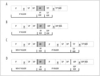
In Figure 1, sections A and B show the location of the AH header in transport mode. Sections C) and D show the location of the AH header in tunnel mode. The data field in all packets is not to scale (indicated by the double slanted lines). You can see from this figure that tunnel mode AH adds an additional 20 bytes to the length of each packet. None of the fields in this figure are encrypted.
| Note |
The key to the incompatibility of NAT and IPsec AH is the presence of the ICV, whose value depends partially on the values of the source and destination IP addresses, the IP header checksum, and either the TCP or UDP header checksum. The AH ICV calculation takes into account the mutable and predictable header fields that change as the packet moves from hop to hop through the network, but because intermediate devices do not share the secret key, they cannot recalculate the correct ICV after NAT has altered the aforementioned original header fields.
|
ESP, on the other hand, was used initially only for encryption; authentication functionality was subsequently added. The ESP header is inserted after the IP header and before the upper layer protocol header (transport mode) or before an encapsulated IP header (tunnel mode).
Figure 2 shows the location of the ESP header in both transport mode (sections A and B) and tunnel mode (sections C) and D) for TCP (sections A and C) and UDP (sections B and D). In transport mode, the original IP header is followed by the ESP header. The rightmost field contains the ESP trailer and optionally, the ESP authorization field. Only the upper-layer protocol header, data, and the ESP trailer (also, optionally, the ESP authorization field) is encrypted. The IP header is not encrypted.
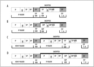
In transport mode, ESP encrypts the entire packet. This means that the entire original IP datagram, including the original IP and protocol header, is encrypted. In this mode, when IP traffic moves between gateways, the outer, unencrypted IP header contains the IP addresses of the penultimate source and destination gateways, and the inner, encrypted IP header contains the IP source and destination addresses of the true endpoints. However, even though ESP encrypts most of the IP datagram in either transport or tunnel mode, ESP is relatively compatible with NAT, since ESP does not incorporate the IP source and destination addresses in its keyed message integrity check. Still, ESP has a dependency on TCP and UDP checksum integrity through inclusion of the pseudo-header in the calculation. As a result, when checksums are calculated, they will be invalidated by passage through a NAT device (except in some cases where the UDP checksum is set to zero).
NAT traversal using ESP leads to a catch-22. NAT must recalculate the TCP header checksums used to verify packet integrity, because as was showed earlier, NAT modifies those headers. If NAT updates the header checksum, ESP authentication will fail. If NAT does not update the checksum, TCP verification will fail. One way around this, if the transport endpoint is under your control, is to turn off checksum verification, but I’m not aware of anyone who has done this in production environments. A second, more common means to do this is to NAT before IPSec; don’t perform IPSec before NAT. This can be accomplished by locating the NAT device logically behind the IPsec device. The most common form of NAT traversal used today relies on encapsulating IPsec packets in UDP in order to bypass NAT devices. The IPsec packet is encapsulated in a meta-UDP packet and the meta
UDP packet is stripped off after it passes through the NAT device. This enables NAT and IPsec to function together but none of these are hardly elegant solutions.


