As the PSTN’s global reach and capabilities become more extensive, signaling became the most significant security concern within the PSTN. In its early days, signaling was no more complicated than taking the phone off-hook to let an operator know you wanted to make a call. Dialing gradually became more automatic, first for operators, then later for subscribers. Today’s direct-dial networks, VoIP gateways, and myriad protocols only serve to increase the complexities and risks when it comes to signaling.
Electromechanical automated switching equipment first appeared in 1891 following Almon Strowger’s patented Step by Step (SXS) system, although Bell System resistance to it would postpone its adoption for decades. The classic rotary dial phone was another Strowger invention that was finally adopted by the Bell System in 1919 along with SXS switches. Yet it would take until 1938 for Western Electric (the equipment R&D arm of the Bell system) to develop a superior automatic switching system, namely the crossbar switch. And not until the 1950s did Bell Labs embark on a computer-controlled switch project, but the 101 ESS PBX that resulted in 1963 was only partially digital. Also introduced that year was the T1 circuit and Touch Tones, the Dual-Tone Multi-Frequency (DTMF) dialing scheme that is still with us today. Despite the fact that switching itself was analog, digital T1 circuits quickly replaced analog backbone toll circuits and most analog CO interconnect trunks. By 1965 Bell had released the first central office switch with computerized stored program control, the 1ESS that offered new features like speed dialing and call forwarding. Yet the 1ESS was still an analog switch at its core. Thanks to T1 “robbed bit” signaling, however, all signaling was out of band, at least from the phone phreaker’s perspective.
Insiders suggest that AT&T was prepared to postpone true digital switching until the 1990s, but Northern Telecom changed their plans with the DMS-10 all-digital switch, introduced in the late 1970s. The need for an all-digital AT&T alternative drove development of the 5ESS and accelerated implementation of ISDN. Today, the most common Class 5 (central office) switches in North America are the Nortel DMS-100 and Lucent 5ESS, running ITU-T Signaling System Number 7 (SS7) with full ISDN support.
The Class 5 switch is the first point where we can find the full suite of telephone services being handled in one place as part of the Intelligent Network model. A typical Class 5 can handle operator services, call waiting, long distance, ISDN, and other data services. The Class 5 will have tables that are queried for every service and will send the appropriate request to the right place. For instance, when you pick up the phone in your house to make a long distance phone call, the Class 5 switch detects the line is open and provides a timeslot in the switch for your call (this is when you hear the dial tone), then based on the buttons pushed (dialed) the switch will send the call either to the local carrier or to the long distance provider. If you dial a long distance call from a provider who is not your local provider, the switch will deliver the request to the closest switch that handles calls for that particular carrier. Class 5 switches act on demand (i.e., they set up, sustain, and tear down connections as needed). This helps to reduce the amount of traffic over the lines when not needed, thus expanding the overall capacity of the system. These switches are a real workhorse for telephone companies (LECs, CLECs, and even IXCs, though they can use a Class 4 switch in most cases). A Class 5 switch can handle thousands of connections per minute.
The Intelligent Network (IN), Private Integrated Services, ISDN, and QSIG
The model drawn up in the 1980s and 1990s for advanced network functionality is called the Intelligent Network (IN). Services such as 8XX-number lookups as well as Calling Cards, Private Integrated Services Network (PISNs), and many other advanced services are all made possible through SS7, ISDN, and IN capabilities. PISNs are geographically disparate networks that are connected via leased lines that allow for enhanced services such as multivendor PBX deployments, Voice VPNs (don’t get these confused with data VPNs, they are a true private network for voice, just like that provided by a PBX), and even certain kinds of VoIP. A Private Integrated service Network Exchange (PINX) lives within a PISN. Another application is integration with the QSIG protocol, which allows PBX products from other vendors be able to be used transparently to integrate all voice networks.
QSIG (a Q.931 ISDN extension) as a protocol has been around since the early to mid 1990s. But QSIG can be used to integrate systems even without ISDN. QSIG also leverages DPNSS, which was developed prior to when the final QSIG protocol was agreed upon. Not used much in U.S. networks, DPNSS had much of its life in the United Kingdom. Modern networks are using QSIG as the means to interconnect voice channels between PBXs while preserving critical information about caller and call state in the process.
ISDN is a common-channel signaling (CCS) solution that works with media or data traveling down one pair of wires while signaling control is handled over another. Remembering back to our earlier discussions of the channels of 64 kbps in size, a typical ISDN will hold 23 bearer (B) channels that carry voice and data and one data (D) channel that carries signaling information. All channels are 64kbps, so we have 24, 64-kbps channels totaling 1536 Mbps, or equivalent to a T1 and 30 B channels plus a D channel on an E-1, but in each case we lose one channel for signaling. Not only was distance from the central office a new issue with ISDN trunks, but the customer also had to implement new equipment. This Customer Premise Equipment (CPE) required ISDN terminators in order to access the network. Today the use of ISDN in the provisioning and delivery of broadband Internet access via DSL and cable services keep pricing competitive and affordable. Besides its use in the DSL services, ISDN still has an active share in providing redundant and emergency data network access to critical servers and services when higher speed lines or primary access has been disrupted.
Over the last 100 years, signaling has moved from operator-assisted modes to loop and disconnect modes, from single frequency to multifrequency signaling, and now to common channel signaling using the ISDN signaling channel.
ITU-T Signaling System Number 7 (SS7)
SS7 (or C7) is an ITU-T (formerly CCITT) standard that defines how equipment in the PSTN digitally exchange data regarding call setup and routing. Other ITU-T signaling systems are still in use throughout the world, particularly:
- ITU-T 5 CAS with 2VF and a 2400/2600 Hz supervisory tone, plus inter-register codes with Multi-Frequency (MF) tones
- ITU-T [5] R2 is a revision of ITU-T 5 but uses different frequencies
What sets SS7 apart above all is the fact that it is Common Channel Signaling (CCS), not CAS like its predecessors. Throughout the telecommunications industry the SS7 can be used for call session setup, management and tear down, call forwarding, caller identification information, toll free, LNP, and other service as implemented by carriers. Information passed through SS7 networks are communicated completely out of band meaning that signaling and media do not travel down the same path. The SS7 was loosely designed around the OSI 7-layer model. Figure 1 illustrates their basic similarities.

Message Transfer Parts 1, 2, and 3 (MTP)
MTP level 1 is much the same as the Physical layer (1) of the OSI. Here the electrical and physical characteristics of the digital signaling are addressed. The physical interfaces defined here are those such as our previously discussed DS0 and T1. MTP level 2 aligns with the Data Link layer of the OSI. MTP level 2 takes care of making sure transmissions are accurate from end to end, just like the Data Link layer issues such as flow control and error checking are handled in the MTP level 2 area. MTP level 3 aligns itself with the Network layer of the OSI. MTP level 3 reroutes calls away from failed links and controls signaling when congestion is present.
Telephone User Part (TUP)
This is an analog system component. Prior to digital signaling the TUP was used to set up and tear down calls. Today most countries are using the ISDN User Part (ISUP) to handle this requirement.
ISDN User Part (ISUP)
Most countries are using ISUP to handle basic call components. ISUP works by defining the protocols used to manage calls between calling and called parties.
Automatic Number Identification (ANI), or—when it’s passed on to a subscriber, known as Calling Party Identification Presentation (CLIP)—caller ID is passed to the PSTN (or back again) through ISDN trunks and displays the calling party’s telephone number at the called party’s telephone set during the ring cycle. ANI is used for all Custom Local Area Signaling Services (CLASS) such as custom ringing, selective call forwarding, call blocking, and so on.
Signaling Connection Control Part (SCCP)
The SCCP is used mainly for translating 800, calling card, and mobile telephone numbers into a set single point destination code.
Transaction Capabilities Applications Part (TCAP)
TCAP supports the passing and exchange of data within noncircuit-related communications. An example of noncircuit-related data is authentication of a user to a calling card plan.
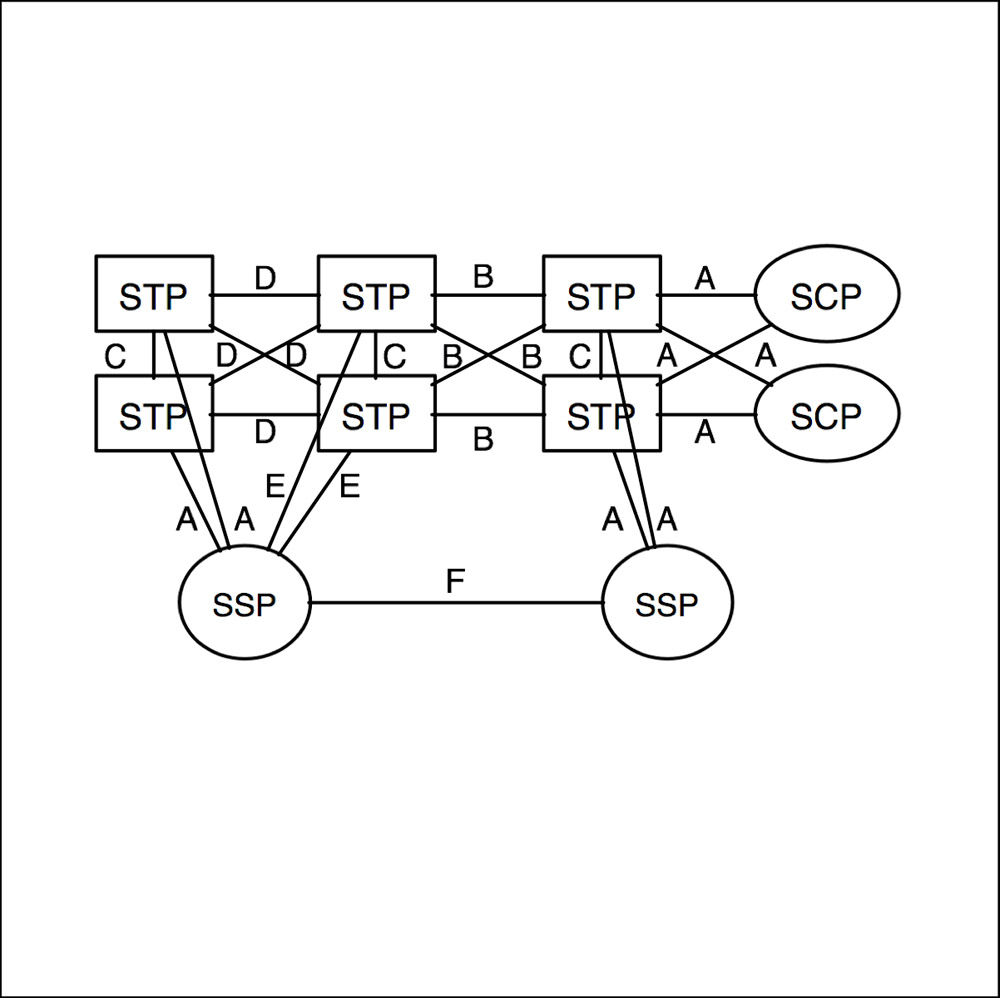
Communication within an SS7 network and its equipment are called signaling points, of which there are three; Service Switching Points (SSP), Service Transfer Points (STP), and Service Control Points (SCP).
Service Switching Points (SSPs) are the primary calling switches; they set up, manage, and terminate calls. When calls need to be routed outside of the SSP’s trunk group a request may be sent to a Service Control Point (SCP), which is a database that responds to queries and sends routing information to requesting switches that delivery the appropriate route for the type of call placed. A Service Transport Point (STP) is a packet switch that forwards messages down the appropriate link depending on the information contained within the packet.
Figure 1 shows basic OSI and SS7 stacks. Links between the SS7 network are broken down into six different types, lettered A through F. Figure 2 illustrates a typical SS7 network topology with specific link type labeled. Table 1 describes each link.
Link Name | Function | Description |
|---|---|---|
A | Access | Connects signal endpoints to an STP |
B | Bridge | Connects peering STPs |
C | Cross | Connects STPs into pairs to improve reliability |
D | Diagonal | Essentially same as B |
E | Extended | Used if A links are not available |
F | Fully Associated | Direct connection of two endpoints (SSPs) |
SS7 can also be run on IP networks using SCTP, using a slightly different stack that includes SCTP transport (instead of TCP or UDP).
SS7 has important security considerations, particularly between carriers where misconfigured implementations with unverified data can open the door to large scale fraud and other risks. The bottom line is that SS7 is a peer-to-peer protocol that may be out-of-band for phone phreaks, but carries significant risk from other sources, especially if it’s running unencrypted over IP through SIGTRAN (SCTP).
1 comment:
thank you for the post , visit us for
best telephone solution for business
Post a Comment